Thermal Management Technology of Water Disinfection Reactor
Thermal Management Technology
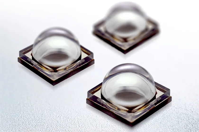
For disinfection products with UV-C LEDs, thermal management of LEDs is one of the technical issues to be solved for designing such things as modules and finished products. Power inputted to an LED is converted to energy of light and heat, and any energy other than that outputted as light is lost as heat. This lost heat causes the temperature of the component to rise and shortens the life of the LED. Therefore, thermal management technology that includes the substrate where the LED is mounted and the surrounding module is a key point to maintaining highly efficient and high quality LED performance.
UV-C LED Reactor Heat Dissipation
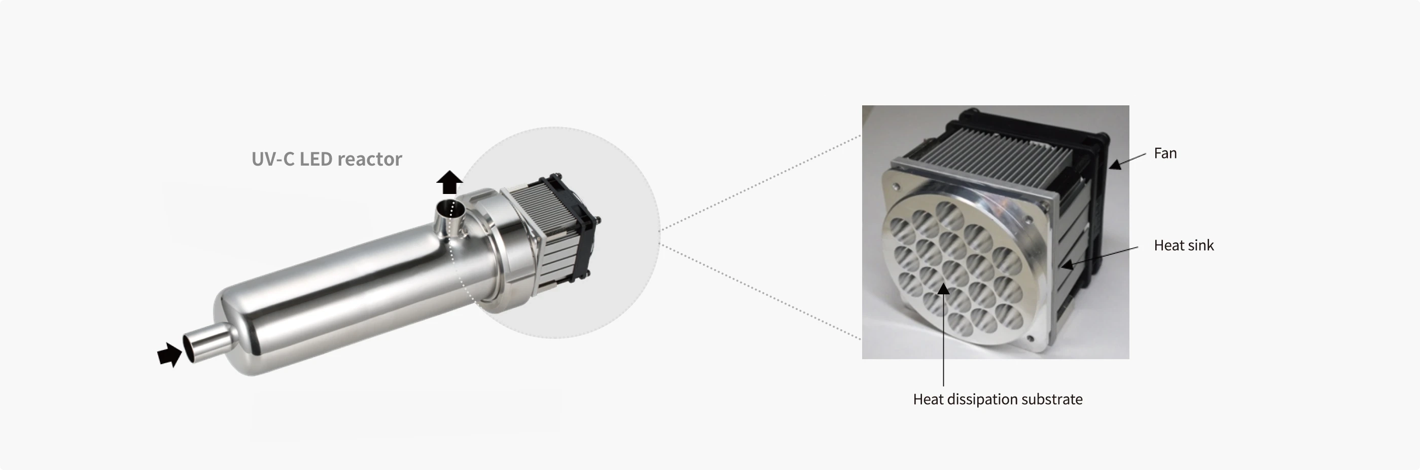
The UV-C LED reactor has three components to dissipate heat. A heat dissipation substrate to supply power to the LED while simultaneously allowing heat to escape, and a metallic heat sink that discharges heat efficiently. These two components are used as electronic devices for personal computers. The third is a fan used to improve the heat dissipation performance by directly blowing air onto the heat sink. Appropriate thermal management is achieved by combining these three parts to maximize their performance.
Fig.1: The Three Heat Dissipation Components
To Achieve Downsizing and Lightweight of Heat Dissipation Parts
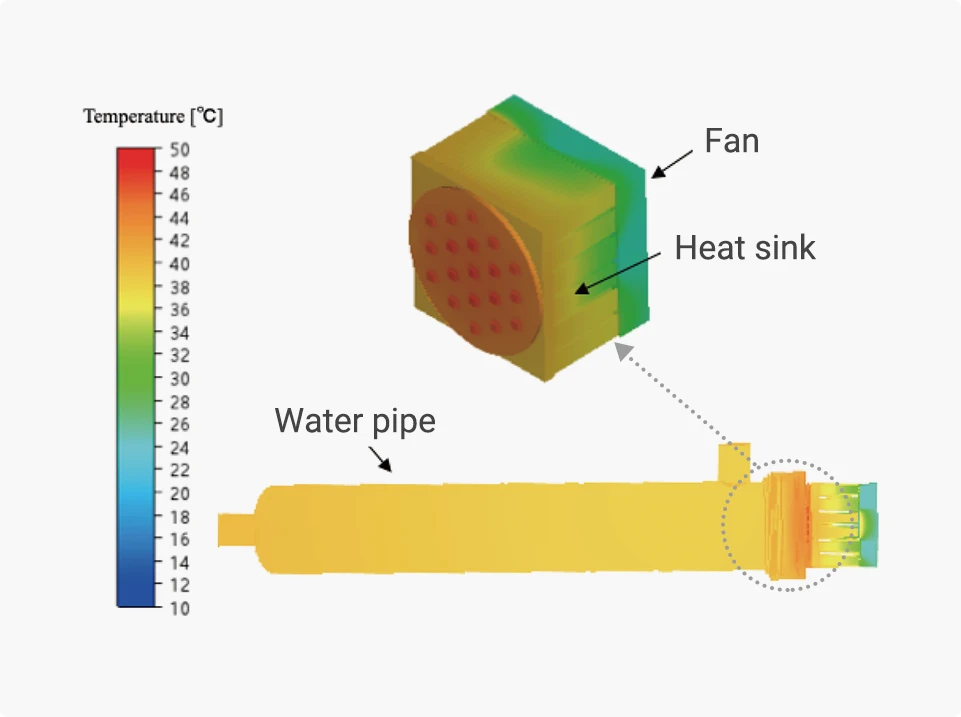
Stanley Electric has implemented theoretical design and thermal fluid analysis based on the theory of fluid dynamics and heat transfer optics at the stage before creating the shape as an object in order to optimize the heat dissipation path of the entire system. We have used a simulation to analyze a system that can easily transfer heat between components and efficiently dissipate heat to the external air [See Fig.2].
Stanley Electric has pursued technology to advance performance while making components as small and light as possible to meet the needs of automotive headlamps. And this technology is adopted in UV-C LED reactors to optimize the shape and their functional characteristics.
Fig.2: An Image Showing Thermal Fluid Simulation Analysis
Related Information
-
Light Source Technology
-

Water Disinfection
-

Surface and Air Disinfection